From Device Physics to System Stability — An Engineering Perspective on Gate Constraint in Cascode Structures
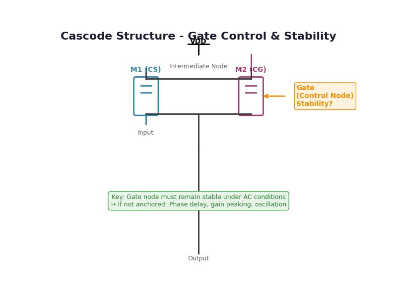
Table of Contents
From Device Physics to System Stability — An Engineering Perspective on Gate Constraint in Cascode Structures
Harry Yin (尹文斌)
Senior RFIC Design Engineer
Focused on RF front-end and analog architectures
Abstract
In analog and RF circuit design, the cascode structure is almost a “default choice” due to its advantages in gain, output impedance, and isolation. It is widely used in LNAs, PAs, and various high-performance amplifiers. However, in practical engineering work, designers often encounter a familiar situation: the topology is correct, the biasing looks fine, yet the simulation or measurement results still feel “off,” sometimes even showing unexpected behavior at certain frequencies.
In many cases, these issues do not stem from the topology itself, but from a more subtle factor—the dynamic behavior of the control node (gate/base) of the common-gate (CG) device. This article revisits cascode structures from a device-level perspective and shares practical insights into where stability really comes from, along with commonly used engineering approaches.
1. Introduction
In most textbooks, the cascode is presented as a clean and effective structure: it improves output impedance and suppresses Miller effects by stacking a common-gate (or common-base) device on top of a gain transistor. While this abstraction works well under ideal or low-frequency conditions, real silicon implementations—especially in RF designs—often tell a more complicated story.
A question that frequently arises during design, but is not always explicitly discussed, is:
Does the performance of a cascode come from the structure itself, or from certain implicit conditions behind it?
As operating frequency increases, this question quickly shifts from theoretical curiosity to a practical design concern.
2. The Physical Nature of Cascode (An Engineering View)
From an engineering standpoint, a cascode is better understood as a local feedback structure, rather than just a stacked topology.
The lower device (CS/CE) generates the signal current
The upper device (CG/CB) constrains the intermediate node through its control terminal
Together, they form a fast local regulation mechanism
Under ideal conditions, this regulation is very effective: the intermediate node (source/emitter) remains nearly constant, leading to high output impedance and good isolation.
However, this behavior relies on an implicit assumption:
The control node of the upper device remains stable under AC conditions.
Once this assumption no longer holds, the “clamping” behavior begins to degrade.
3. A Key Difference Between MOS and BJT
In practice, it is often observed that BJT cascode implementations appear more robust, while MOS-based cascodes require more careful handling. From a device perspective, this difference is quite natural:
The MOS gate is essentially a high-impedance capacitive node
The BJT base, in contrast, provides a low-impedance path with real current flow
This leads to an important distinction:
In MOS, coupled signals tend to translate directly into voltage variations
In BJT, disturbances are more likely absorbed as current, with limited voltage change
As a result:
The control node in MOS is more likely to participate in dynamic behavior, while BJT is inherently more “anchored.”
This is why, in many MOS cascode designs, engineers pay particular attention to how the gate is treated.
4. A Gradual but Critical Dynamic Effect
When the CG gate is not properly “anchored,” the resulting issue does not usually appear abruptly. Instead, it evolves with frequency:
- At low frequencies:
the gate can follow through the bias network and behaves close to AC ground
- At mid frequencies:
the response of the gate begins to lag, introducing phase delay
- At higher frequencies:
the gate behaves more like a charge-storage node with memory
At this stage, a somewhat counterintuitive effect may occur:
The feedback signal that is supposed to stabilize the intermediate node becomes time-misaligned, and in certain frequency ranges, it may even reinforce the disturbance instead of suppressing it.
In simulations, this typically shows up as:
Gain peaking
Ringing in transient response
In severe cases, signs of oscillation
These effects are often difficult to fix through simple parameter tuning, because the root cause lies in timing and phase, not just magnitude.
5. A More Practical Way to Look at It
From an engineering perspective, this behavior can be summarized more simply:
Stability in a cascode is not just about having feedback,
but about whether that feedback arrives at the right time.
Once the control node starts to “remember the past” (due to capacitive effects), the system shifts from static regulation to dynamic participation—and that is often where problems begin.
6. Common Engineering Practices
In real product design, engineers rarely leave this behavior uncontrolled. Instead, several practical techniques are commonly applied:
6.1 Making the Control Node “Harder to Move”
Adding decoupling capacitance and reducing AC impedance helps keep the node close to AC ground over the frequency band of interest.
6.2 Strengthening the Bias Network
Lowering the effective impedance of the bias path reduces the likelihood that coupled signals translate into voltage variations.
6.3 Introducing Controlled Damping
Techniques such as source degeneration or small resistive elements may slightly reduce gain but significantly improve phase behavior.
6.4 Thinking at the System Level
In RF designs, matching networks do more than just power transfer—they also shape frequency response and indirectly affect stability.
7. Observations from PA and LNA Design
From practical experience:
LNAs are highly sensitive to isolation and reverse gain, making control node stability critical
PAs deal with large-signal behavior and energy flow, where dynamic effects can quickly become problematic
Despite different priorities, both share a common reality:
A cascode is not inherently stable—it is a structure that performs well only when properly constrained.
8. Conclusion
From device physics to system behavior, the stability of a cascode structure is not guaranteed by topology alone. The dynamic behavior of its control node plays a critical, and often underestimated, role.
In simple terms:
If the control node remains sufficiently “quiet,” the circuit behaves close to ideal
Once it starts to participate dynamically, the behavior becomes significantly more complex
9. An Engineering Takeaway
In practical design,
instead of only asking “Is this the right structure?”,
it is often more useful to ask:
“Is there a node moving when it shouldn’t?”
More often than not, the answer leads directly to the root cause.
This note reflects practical engineering experience and is intended as a conceptual reference for designers working with cascode-based architectures.
About the Author
Harry Yin is a Senior RFIC Design Engineer with experience in PA, LNA, RF switches, and analog circuits. His work focuses on RF front-end architectures and system-level trade-offs in communication IC design.