Understanding Coupling in On-Chip Spiral Inductors
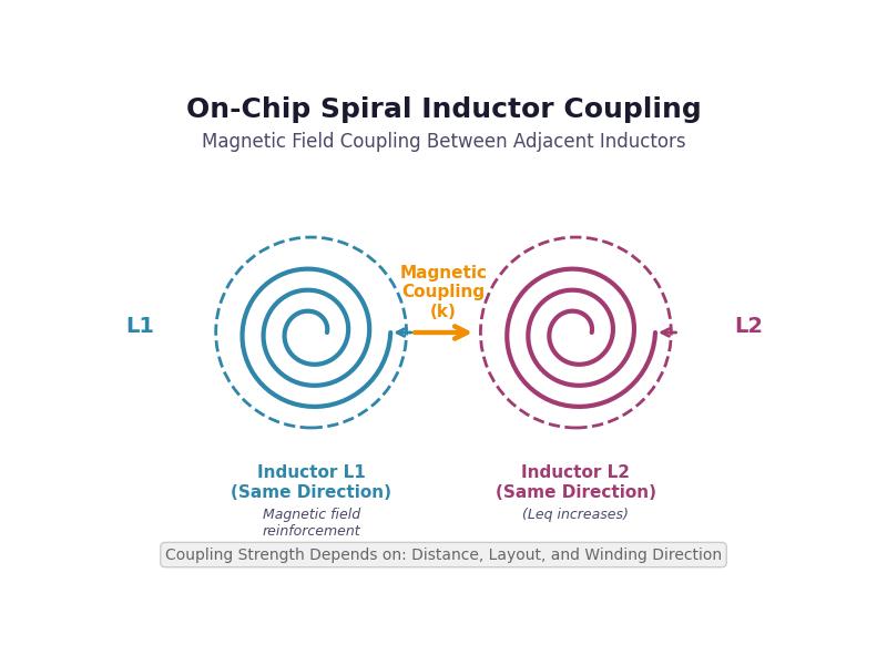
Table of Contents
Understanding Coupling in On-Chip Spiral Inductors
Harry Yin (尹文斌)
Senior RFIC Design Engineer
Focused on RF front-end and analog architectures
Overview
In our RF IC designs, we frequently encounter coupling effects between on-chip spiral inductors, especially as layouts become more compact and integration levels continue to increase.
On-chip spiral inductors are widely used in matching networks, oscillators, and transformer-based circuits. When multiple inductors are placed close to each other on silicon, they naturally interact through magnetic coupling, which can significantly change the effective inductance seen by the circuit.
In practice, this coupling is not always a drawback—it can either be intentionally utilized or carefully minimized, depending on the design objective. This article explains how it works and how to approach it from a layout and circuit design perspective.
1. Basic Concept
When two inductors are placed close enough to influence each other, they can no longer be treated as independent components. Instead, their combined behavior is described by:
$$L_{eq} = L_1 + L_2 \pm 2M$$
where:
$$M = k \times \sqrt{L_1 \times L_2}$$
k: coupling coefficient (ranges from 0 to 1 in magnitude)
M: mutual inductance From a practical point of view, two key factors determine the final behavior:
Coupling strength → mainly determined by layout and spacing
Coupling polarity → determined by winding direction
2. Winding Direction: Positive vs. Negative Coupling
The winding direction of a spiral inductor (clockwise or counterclockwise) defines the direction of the magnetic field according to the right-hand rule.
Same Direction (Positive Coupling)
When both inductors have the same winding direction:
- Their magnetic fields reinforce each other
- Mutual inductance is positive (M > 0)
- The effective inductance increases This type of coupling is commonly used in transformer-based designs.
Opposite Direction (Negative Coupling)
When one inductor is flipped:
- The magnetic fields oppose each other
- Mutual inductance is negative (M < 0)
- The effective inductance decreases This can be useful when reducing inductance or compensating for unwanted coupling.
Key Takeaway:
Winding direction does not affect how strong the coupling is—it only determines whether the interaction is constructive or destructive.
3. Distance and Layout: What Controls Coupling Strength
While winding direction controls the sign of coupling, the physical layout determines how strong the coupling is.
As inductors are placed closer together, the overlap of their magnetic fields increases, leading to a higher coupling coefficient k.
Typical Coupling Ranges in Practice
| Layout Condition | Coupling Coefficient (k) |
|---|---|
| Far apart | <0.05 |
| Moderate spacing | 0.1-0.4 |
| Very close | 0.4-0.7 |
| Stacked | 0.6-0.9 |
Common Layout Configurations
Side-by-side (same metal layer)
- Coupling mainly occurs through fringe magnetic fields
- Moderate coupling strength
- Easier to control and tune
Stacked (different metal layers)
- Strong magnetic field overlap
- High coupling efficiency
- Commonly used in on-chip transformer implementations
4. Design Guidelines
In real designs, inductive coupling is something you either leverage or manage.
When Strong Coupling Is Desired
- Use the same winding direction
- Place inductors close together
- Consider stacked configurations Typical use case: on-chip transformers
When Coupling Should Be Minimized
- Increase spacing between inductors
- Avoid unnecessary overlap
- Use shielding or guard structures if needed
When Coupling Needs to Be Cancelled
- Use opposite winding directions
- Useful for:
- Reducing effective inductance
- Suppressing unwanted interactions
- Improving isolation in sensitive RF blocks
5. Summary
The behavior of coupled inductors can be understood in a very intuitive way:
- Geometry (distance and layout) determines how strong the coupling is
- Winding direction determines whether the coupling adds or cancels Or more simply:
Coupling strength comes from geometry, while coupling polarity comes from direction.
Final Note
In modern RF IC design, coupling between inductors is almost unavoidable due to layout constraints. Rather than trying to eliminate it entirely, a better approach is to understand it well and make it work in your favor—or at least keep it under control.